Gear
Coupling
As one of the leading gear coupling manufacturers, mechanical product suppliers, and exporters, we supply gear coupling and many other products for cluster gear coupling.
About SSJ Group
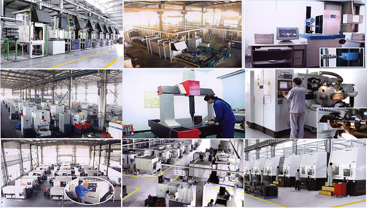
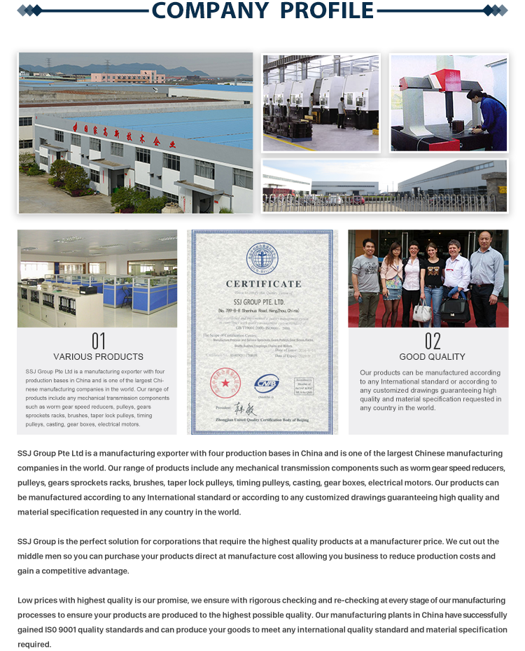
SSJ Group is the leading manufacturer, a supplier specializing in the production of various transmission parts. Such as sprocket, chain, pulley, couplings, gears, flexible gear coupling, rigid coupling, brake drum gear coupling, nylon gear coupling, pin bush coupling, tire coupling, chain coupling, worm & worm wheel, bevel gear, spur gear & All kinds of transmission machinery spare parts.
Furthermore, we can produce customized variators, geared motors, electric motors, and other hydraulic products according to customers’ drawings. We have exported our products to clients worldwide and earned a good reputation because of our superior product quality and after-sales service. We warmly welcome customers both at home and abroad to contact us to negotiate business, exchange information, and cooperate with us.
Our Product
What are Gear couplings?
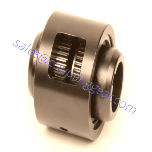
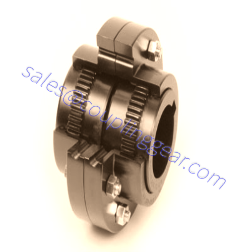
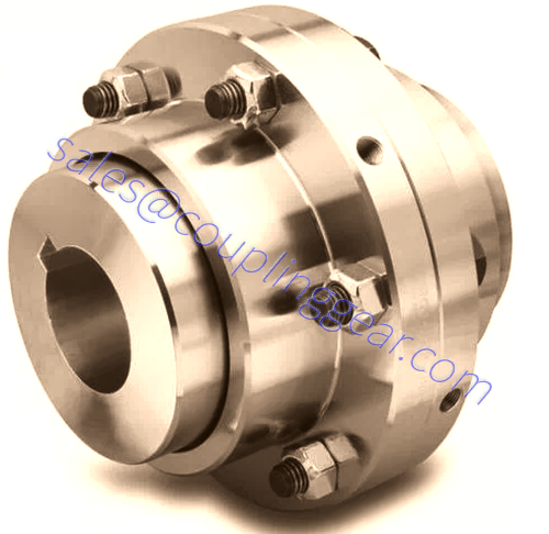
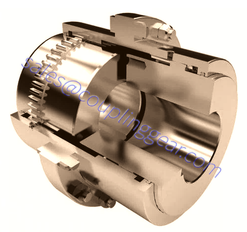
A gear coupling is a type of flexible coupling intended to connect two shafts at their ends to transmit power, to transfer rotational movement from one post to another. Available in a wide range of sizes, they can transmit high torque at high speed. Each coupling consists of 2 two hubs with external gear teeth, corners are joined by flange sleeves with internal gear teeth, and flanges are bolted together. There are three types of teeth designs used in gear couplings: straight teeth, crowned with a constant radius, crowned with a variable radius. The collar is customarily enclosed. Coupling parts include gaskets and O-rings to prevent the lubricant leakage filled inside the coupling. General-purpose gear couplings are usually made from carbon steel. Because of their design, these torsionally stiff couplings can withstand some shock loading, but they cannot absorb significant amounts of it.
Gear couplings have a general misalignment capability of 0.01-0.02 inches in parallel and 2 degrees in angular. They are sometimes used in pairs of spacer shafts to bridge the gap between driving and driven machinery. They are usually lubricant-required, but some are designed for lighter-duty use lubricant-free nylons or other polymers for the center sleeve.
Benefits of using Gear Couplings
- High torque density
- Three types of misalignment (angular, parallel, axial)
- High torque at high speeds
Gear couplings are commonly used in metal industry steel or wire mills applications. They provide significant value in places where high torque to size ratio is necessary, as well as high-speed capabilities.
Feel free to Contact Us if you have any questions, need more information or if you are interested in purchasing a coupling. We can offer you standard off-the-shelf couplings or design a unique collar to meet your requirements.
Full Gear Couplings
Feature
1. Gear gap is relatively large, allowing a more significant angular displacement.Improve torque transfer and prolong service life.
2. Radial, axial and angular compensation capabilities.
3. Compact structure, high transmission efficiency and low noise.
4. Use for low speed and heavy load environment.For example: mining equipment, chemical industry, general, etc., etc.
Full gear coupling Model
FGC10- bore diameter X bore length – bore diameter X bore length (mm)
FGC10-100X212-120X200
FGC:Full Gear Coupling

Half Gear Couplings
Summary:
1.Gear type coupling has compact structure and large bearing capacity.
2.Wide range of speed, reliable work.
3.It is used in mining, hoisting, shipping and other industries.
Half Gear Coupling Model:
HGC10- bore diameter X bore length – bore diameter X bore length (mm)
HGC8-80X142-70X100
HGC:Full Gear Coupling
8: The size of the code
one side: bore diameter80mm ; bore length 142mm
other side: bore diameter 70mm ; bore length 100mm
Flanged Sleeve Gear Couplings
This type of coupling can deliver the highest torque levels out of our range and offers very competitive performance in each size series because of the extensive design and engineering.
This gear coupling is easy to maintain and install to increase its reliability within customers’ applications.

Continuous Sleeve Gear Couplings
This gear coupling is very compact and designed for maximum torque transmission in the smallest space margins, which is essential for some applications.
The efficient design means the minimum number of components, which gives greater simplicity to our customer’s applications, improving reliability and reducing maintenance downtime.
Continuous sleeve type gear couplings are best utilized in small operating windows and limited space mechanical drive applications but that have very high torque transmission requirements.
Nylon gear coupling
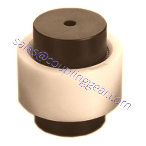
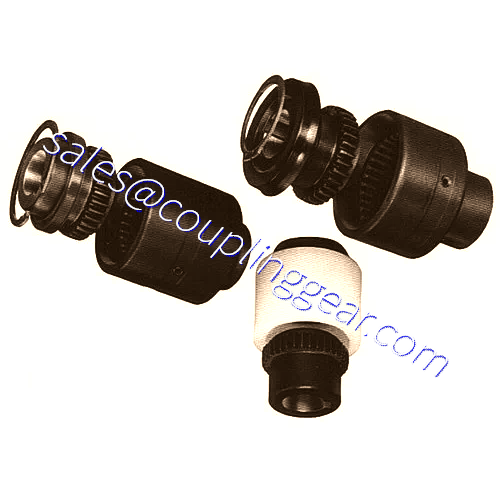
A nylon gear coupling is a range of collars made of two steel, crowned teeth hubs, which are connected with a polyamide internally toothed sleeve. The unique new design of the crowned teeth hubs and the lubrication-free combination of steel with polyamide ensure good sliding properties and lead to low maintenance and low wear operation, with substantial axial, angular and radial misalignment of the shafts. A nylon gear coupling is resistant to all types of lubricants and hydraulic fluids and can be used at -25°C +80°C.
Advantages of nylon gear coupling
- The easiest and cheapest coupling on the market
- Ideal for the transmission of small torque, high-speed
- Low maintenance
- High ability to compensate for misalignments

Gear Coupling Installation:
Gear Couplings are designed to provide a mechanical connection between the rotating shafts of mechanical equipment, using gear mesh accommodate inherent misalignment while transmitting the power and torque between the connected shaft.
1) Mount Flanged Sleeves, Seals and Hub
- Examine the coupling assembly to insure there is no visible damage.
- Clean the hub bores and shafts using lint free cloth. Remove any nicks or burrs.
- When assembled, the keys should have a close side to side fit in the keyways in the hub and shaft with a slight clearance over the top of the keys.
- Place the flanged sleeves with oil rings on shafts before mounting flex hubs.
2) Straight Bore with Clearance / Slip Fit
- Install the keys in the shaft.
- Check to be sure that the set screws in the hub do not protrude into the keyway or the bore. Remove or back out the set screw to provide clearance during assembly.
- Slide the hub up the shaft to the desired axial position.
- Assemble and tighten the set screws using a calibrated torque wrench.
3) Straight Bore with Interference Fit
- Accurately measure the bore and shaft diameters to assure proper fit.
- Install the keys in the shaft.
- Heat the hub (275°F) in an oven until the bore is efficiently larger than the shaft.
- When the hub expanded, install it on the shaft to the desired axial position.
4) Taper Bore
- Check for acceptable contact pattern between the hub and the shaft.
- Put the hub on the shaft, keeping the keyways aligned.
- Lightly tap the face of the hub with a soft mallet. The resultant position will provide a starting point for the hub axial draw up.
- Use a depth micrometer to measure the distance from the shaft end to the hub face, and record the dimension.
- Mount a dial indicator to read axial hub advancement. Alternatively, the indicator can be positioned to contact the end of the hub.
- Remove the hub and install the keys in the shaft.
- Heat the hub (350°F) in an oven until the bore is sufficiently larger than the shaft. Do not exceed 500°F.
- When the hub expanded, install it quickly on the shaft to the “zero” set point. Continue to advance the hub up the taper to the desired axial position.
5) Shaft Alignment
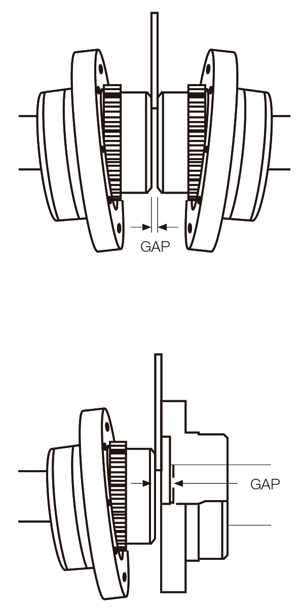
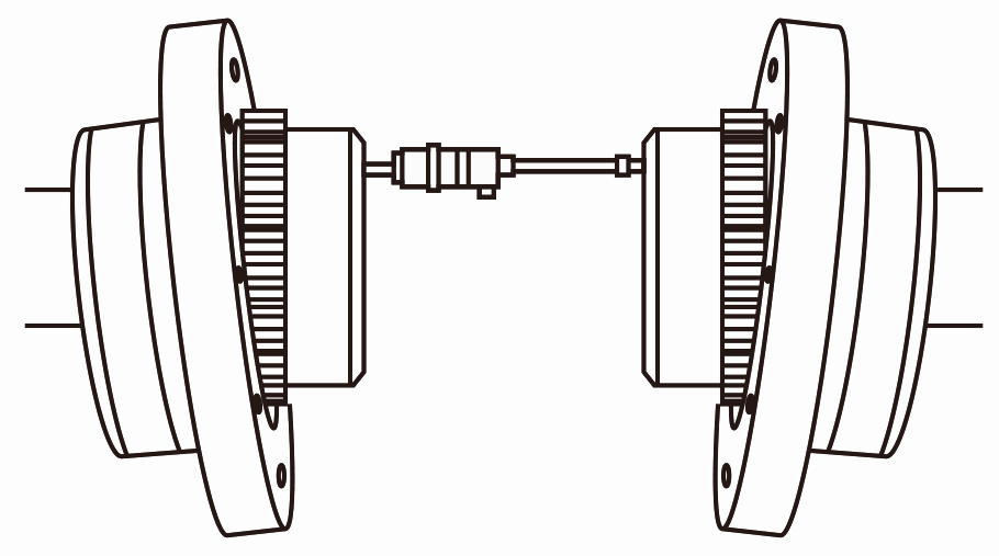
- Use an inside micrometer or a spacer bar equal in thickness and at 90° intervals to measure the distance between hubs to gap.
- The “Angular Misalignment” value is the maximum difference between the measurements X and Y taken at opposite ends of the flanges.
6) Sleeve Installation
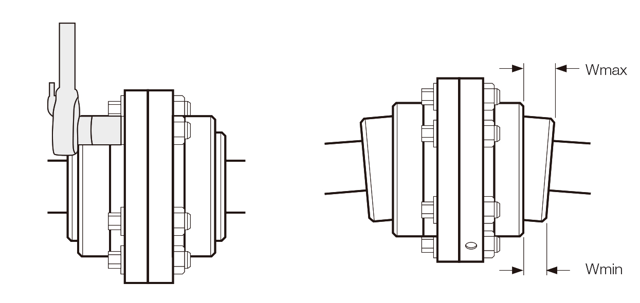
- Insert gasket between flanges and gap disc into counter bore of each rigid hub for floating shaft assemblies, and bolt flanges together.
- Check the alignment of the coupling. Determine “W” by measuring distances “W”max and “W”min between flex hub and sleeve using a depth micrometer or feeler gauges. The difference between “W”max and “W”min must not exceed the “W” value.
- When the hub expanded, install it quickly on the shaft to the “zero” set point. Continue to advance the hub up the taper to the desired axial position.
